Pneumatic fittings are devices and instruments that are powered by compressed air or gas. The concept behind pneumatic fittings can date back to the 1st century A.D. when a simple jet-type compressor has been invented to provide air for smelting and forging. Ideas of utilizing gas as a type of power source were not fully exploited in the following hundreds of years. It was not until the most recent 500 years that pneumatic fittings have witnessed significant popularity in their application. The ever-developing automatic machinery, labor-saving devices, and automatic-control systems have further led to an increase in the use of pneumatic fittings.
Pneumatic fittings generate compressed air themselves and take advantage of the same as its power source. When a pneumatic fitting work, the compressed air generated inside of it is released and its energy is converted to energy of motion. Cylinders, pneumatic motors, steam engines, rock drills, pavement breakers, riveters, forging presses, paint sprayers, blast cleaners, and atomizers are among the most commonly seen pneumatic fittings of the industry.
What Benefits Can Pneumatic Fittings Bring to Operators?
Pneumatic fittings have been put into use in various power and control systems in dentistry, construction, mining, and other areas. They gain their popularity for good reasons, which can be boiled down to the following.
1.Safety At Work
十Power tools are often used in an environment with moisture, dust and conductive metals. These working conditions are not necessarily deadly for workers themselves. However, they can present potential electrical hazards for operators of power tools. When an electric wire is damaged or cut, an electric shock can occur when the tool is being used. A good way to avoid this situation is to remove electric power from the equation by using pneumatic fittings. Pneumatic fittings, far less sensitive to water and dust, will not generate an electrical hazard to the operator.
2.Compact And Ergonomic Design
十Pneumatic fittings are lighter, more powerful and deliver better ergonomics than electric tools. The rule of thumb is that with equivalent power output, a pneumatic motor is 1/6 of the size of an electric motor, and 1/4 of its weight. Pneumatic fittings feature smaller size and lighter weight, resulting in easier handling, faster operation and increased productivity and making them ideal alternatives to electric tools under circumstances where portability is underlined.

3.Improved Productivity
十Besides durability and ergonomics, working with pneumatic fittings translates into improved productivity. Pneumatic fittings are built for the most intensive usage and are vital players in industrial environments. Because of the great power-to-weight ratio, pneumatic fittings are able to produce more horsepower while still being lightweight and compact. For electric tools, only 50% to 60% of power fed into the motors are converted to output power. However, for pneumatic fittings, 100% of the input power is convertible into output power. Therefore, pneumatic fittings deliver more torque and higher revolutions per minute (RPM), allowing operators to complete their tasks in a more efficient manner. Moreover, when well maintained and lubricated, pneumatic fittings can work continuously around the clock. Compared with electric tools, pneumatic fittings are free from many other external factors that will affect the normal operation and save both time and costs for maintenance.
4.Durable And Constant Performance
十Pneumatic fittings are not disposable or single-use pieces of equipment that need frequent replacement – you can depend on them for durable and constant operation. More importantly, the manufacturing industry of pneumatic fittings has sidestepped a problem of long-standing that the lack of a specific spare part may risk invalidating an entire tool. Most pneumatic fittings have been specifically designed for ease of maintenance, and all original spare parts are available and organized in tune-up kits for fast ordering and replacement. Ultimately, the less time spent performing maintenance and equipment upgrading and replacement means more time for productive material removal, faster return on investment and revenue.
What Are the Different Categories of Pneumatic Fittings?
Pneumatic fittings can be categorized in various methods according to their different applications, types, functions, etc. In this passage, we divide pneumatic fittings into the four following categories according to the different ways they work.
◪Solenoid valves
◪Pneumatic cylinders
◪Air preparation units
◪Pulse valves
◪Pneumatic vibrators
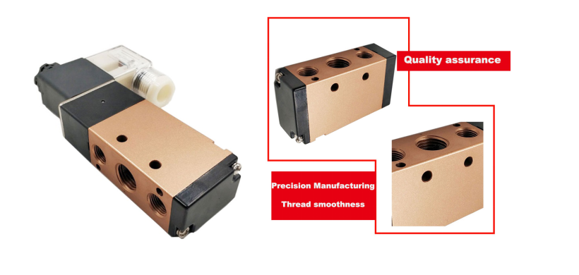
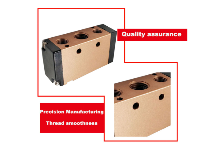
Solenoid valves, a type of automatic pneumatic components controlled by electromagnetism for industrial equipment, are commonly used in industrial control systems to adjust the direction, flow, speed and other parameters of the medium passing through. Solenoid valves are inspired by electromagnetic effect and are controlled by relay devices. In this way, the solenoid valve can be used in different circuits to achieve the desired control with a high degree of accuracy and flexibility.
Solenoid valves fall into different types. Different solenoid valves can play different roles in different positions of the control system. The most commonly used are one-way valves, safety valves, direction control valves, speed control valves and so on. There are closed cavities in solenoid valves. Each of the through-holes in different positions of the valve leads to different pipes. Two electromagnets are on both sides. The electromagnet will be directed to the side where the magnet coil electrifies the body of the valve. By controlling the movement of the body of the valve, different holes can be either open or closed. When a specific hole is open, the fluid that passes through will enter the desired pipe. The pressure of the fluid can push the piston of the cylinder, which will power the piston rod to drive the mechanical devices. In this way, the mechanical movement is controlled by way of controlling the current of the electromagnets.
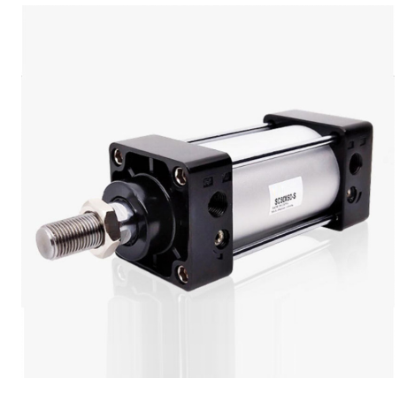
Pneumatic cylinders are a type of pneumatic actuator which converts the energy of compressed gas to energy of motion by pneumatic transmission. Cylinders are widely used in industrial automation control, including for some large power plants, cement plants, and chemical plants, etc. Now, cylinders have become popular actuators in industrial production worldwide. Their wide application has significantly improved the efficiency of industrial production.
A pneumatic cylinder generally consists of a cylinder, an end cover, a piston, a piston rod, and a seal. The commonly used material of a pneumatic cylinder is aluminum alloy. The structure of pneumatic cylinders is simple, making their fabrication process easy. During use, it converts the energy of the compressed gas to energy of motion. They are highlighted by nonpollution, low noise, ease in installation, safety, and the clean and hygienic nature. Compared to other actuators, they are powered by compressed air and require neither electricity nor fuel.
Pneumatic cylinders are mainly used in conjunction with solenoid valves during use and are connected to each other through a gas pipe and a fitting. The pressure in the cylinder is controlled by the switch of the solenoid valve. When the solenoid valve is opened, the cylinder is filled with clean compressed air, the piston is pressed, and the piston rod is pushed forward to reach the designated position and then stop. When the solenoid valve is switched to the other direction, the other side of the piston will be filled with compressed gas. Upon the release of the compressed gas, the piston retracts to guide the piston rod back to realize the motion.
3.Air preparation units
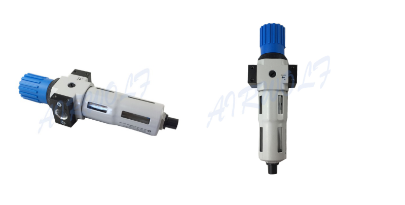
Air preparation units aim to improve the quality of compressed air being fed into pneumatic fittings in order to lengthen their service life as well as control the pressure/flow of shop compressed air. They consist mainly of air filters, air regulators and air lubricators.
An air source processor is a component that works by compressed gas, which converts the energy of compressed air to energy of motion. They have been widely used in metallurgical machinery, construction, transportation equipment, household appliances, light industry, machine tools, medical, packaging and other industries. The compressed air exhausted by air compressors can not be used directly since the compressed air contains a certain amount of water, oil, and dust. Moreover, after being compressed, the temperature of the compressed air can reach 140-170℃, and some water and oil can be in gaseous form. For this very reason, compressed air should be purified before it can be used to operate machinery and equipment.
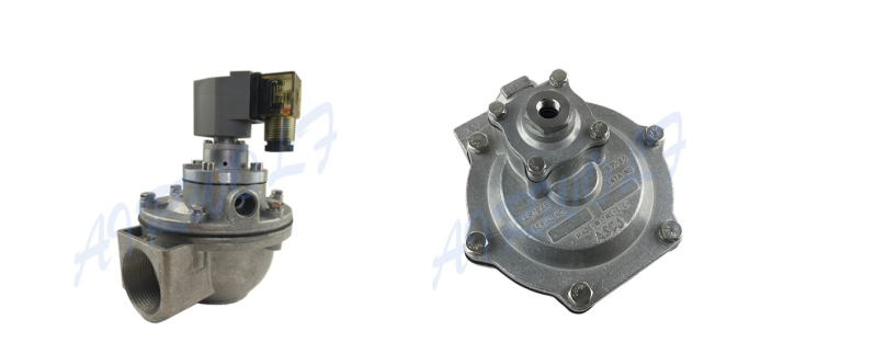
Pulse valves are diaphragm valves controlled by electromagnetic or pneumatic pilot valves, which can instantly open and shut off high-pressure gas source to generate pulses. A pulse valve is a key component of in the dust clean blowing system for pulse bag filters. This system cleans the filter bags cluster by cluster with high-pressure blowing to keep the pressure resistance of the baghouse within a pre-set range, and thus ensure the processing capability and the dust-collecting efficiency of the baghouse.Pulse valves are mainly seen in industrial dust removal equipment for metallurgy, chemical industry, power, machinery and other industries of flue gas, purification, dust control and material retrieving like cement plants, steel plants, and power plants, etc. When energized by an electric signal from the controller, the electromagnetic armature will move to open the discharge opening of the back cavity. The compressed air in back cavity bursts out to release the pressure and pressurized air in front cavity pushes up the diaphragm to open the main outlet of the valve, then the electromagnetic pulse valve opens and starts to blow. When the signal disappears and the spring works immediately to send the pilot operator back to its original position and close the discharging opening. The diaphragm will close the passage by the effect of the pressure in the front cavity and the spring. The pulse valve stops blowing. The orifice in the diaphragm damps the airflow when the armature is lifting up for releasing the pressure. When the discharge hole is closed, the pressure gas will fill into the front cavity to close the passage by the diaphragm and the pulse valve stops blowing.
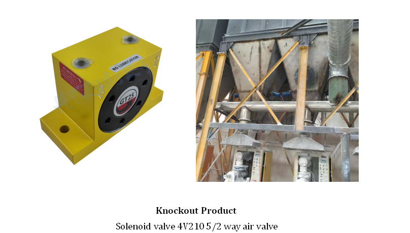
5.Pneumatic vibratorsPneumatic vibrators use the high-pressure gas from the air compressor to enter the product intake through the trachea,It generates power through the motion of the piston. It works on the barn and the wall.
A pneumatic vibrator is a versatile piece of equipment that is essential to a wide range of industries. In construction, for example, the pneumatic vibrator is used to remove excess moisture and pockets of air from freshly poured concrete ensuring that the end result is uniform, attractive and above all, safe. In agriculture, pneumatic vibrators are mainly used to empty silos. In the pharmaceuticals manufacturing industry, a pneumatic vibrator can separate fine powders or be used as a feeding mechanism. Not only does a pneumatic vibrator save time and money, but it can also make tasks safer and easier. Using compressed air as the sole power source, pneumatic vibrators feature low consumption, safety, and energy-saving, and are suitable for freezing, high-temperature, humid, dry, dusty or explosive environment.
Pneumatic vibrators gain popularity owning to small size, less malfunction, easy installation, and maintenance. They can stop or start quickly, suitable for both manual or automatic systems. The vibration force, frequency, and amplitude of pneumatic vibrators can be adjusted by adjusting the air pressure and flow rate in motion. For these advantages, they have been widely used for fatigue test of parts or structures, jitter and compaction of hoppers, linear and bowl feeders, sieves, filters, shaking table and mixing equipment.
Before installing the vibrator, make sure that the installation position is carefully selected to ensure the best working efficiency. The installation surface must be clean and flat. An uneven mounting surface can make the vibrator fail to work normally due to the torsional vibration of the vibrator body. A pneumatic vibrator should be installed as far as possible to make the ball, roller rotation direction of material flow support. The air inlet direction can easily determine the correct installation position.
There are closed chambers at different locations in the solenoid valves. Different holes connect to different pipes. The piston is in the middle of the chamber and two electromagnets are on both sides. The magnet coil electrifying valve body on either side will be attracted to the corresponding side. By controlling the movement of the valve body, different oil discharge holes will be opened or closed. Pressure will accordingly enter different oil discharge pipes, and then push the piston of the cylinder which will subsequently drive the mechanical device. In this way, the mechanical movement is controlled by the current of the electromagnet.
How to Maintain Pneumatic Fittings and Optimize Their Performance?
Pneumatic fittings are mechanical systems including air motors, wear parts (such as vanes, bearings, and seals), and other units. Pneumatic fittings are supposed to and are expected to deliver their desired function and perform at their optimum level for the possibly longest production time. To this end, it necessitates maintaining pneumatic fittings to optimize their performance and preserve their specifications like power and speed. With the right maintenance, pneumatic fittings can offer constant productivity and maximize uptime, avoid unexpected work interruptions and ensure operators’ safety.
Maintenance of pneumatic fittings involves two types of maintenance:
1.Preventive maintenance refers to basic, routine and foreseeable measures that can be taken to reduce the risks of failure of the pneumatic fittings. These measures include regular lubrication and replacing those parts that are estimated to wear out before their downtime.
Preventive maintenance for pneumatic fittings, according to the actual situation of the pneumatic fittings in use, can include the following steps.
a)Ensure the quality and pressure of the air supply. It is important that the source air is clean to prevent jamming of the key components of the pneumatic fittings. Using a filter regulator lubricator (FRL) can also optimize the performance and lifespan of pneumatic fittings.
b)Set up and lubricate as instructed by the manufacturer. Follow manufacturers’ instructions regarding set up, lubrication and wear parts for the pneumatic fittings. Manufacturers’ maintenance manual is supposed to make the process easier. The frequency at which wear parts need replacing will be determined by the fitting specifications and the application, or even directly told by the manufacturers.
c)Optimize downtime as well as uptime. When a pneumatic fitting is taken out of the production line to carry out scheduled maintenance, take advantage of the time to do a detailed check and assessment of the wear of other fittings too. If disassembly and reassembly are required, make sure these are performed in accordance with the manufacturer’s instructions as well as using original and authentic spare units.
d)Store pneumatic fittings well. Pneumatic fittings should be kept in a storage away from damp environments or harsh conditions when they are not being used following the instructions indicated in the manual of the manufacturer.
2.Corrective maintenance refers to measures taken reactively in response to the failure of the pneumatic fittings.
How to Address Commonly Seen Issues in Pneumatic Fittings?
The faults of solenoid valves will directly affect the action of switching valves and regulating valves. In the event of failure to operate normally, the following should be looked into.
a)Failure to operate. Wiring head of the solenoid valve may be loose or the wire head falls off, which caused the solenoid valve not to be electrified. Under such circumstances, the wire head should be tightened.
b)Burnt-out of the coil. Remove the wiring of the solenoid valve and measured with a multimeter. If the coil of the solenoid valve is peeled off, the coil of the solenoid valve will burn out. The reason may be that the coil is damped, resulting in poor insulation, magnetic leakage, and finally excessive current in the coil. Therefore, rainwater should be prevented from entering the solenoid valve. In addition, when the spring is too hard, the reaction force may be excessively large and too little coils turns, leading to insufficient suction. In case of emergency, the button on the coil can be manually switched from the "0" to "1" in normal operation, so the valve can be opened.
c)Jamming. The clearance between the sliding sleeve and the spool of the solenoid valve is very small (less than 0.008mm), and it is generally a single-piece unit. When mechanical impurities are brought in or lubricant is insufficient, the jam is easy to happen. To remove the jam, use a piece of steel wire to poke into the small hole at the head to make it rebound. The fundamental solution is to firstly remove the solenoid valve, then remove the spool and the spool sleeve, and clean it with carbon tetrachloride (CCI4), so that the spool can move flexibly in the valve sleeve. When disassembling, attention should be paid to the assembly sequence and external wiring position of each component in order to reassemble and wiring correctly. Make sure to check whether the oil spray hole is blocked and whether the lubricating oil is enough.
d)Leakage: Leakage will cause insufficient air pressure, which makes it difficult to open and close the valve. This can happen when the sealing gasket is damaged or the sliding valve is worn out, resulting in simultaneous channeling of several cavities. If this fault of the solenoid valve occurs in the switching system, it should be dealt with it when the solenoid valve is out of power. If the process is not completed in a switching gap, the switching system can be suspended and handled calmly.
What Should You Know Before Utilizing Pneumatic Fittings?
Before you make the decision of purchasing and utilizing pneumatic fittings, you may be caught in an age-old dilemma: “Should pneumatic fittings or electric power tools be chosen?” It is essential to understand that one single tool technology is not everything for every application.
The selection of appropriate tools depends on the application and the desired results that are expected to achieve. Each technology has its advantages and disadvantages. Before you decide which to use, ask yourself what you expect the most from a tool. Is it efficiency, power, ergonomics, portability or ease in maintenance? What are your working conditions like? Do you have a supply of quality air source or do you only have access to electrical sockets?
To be specific, when performance is vital for your application, then pneumatic fittings deliver the best results. They provide a better power-to-weight ratio and have a longer service interval, which overall contributes to better performance. Pneumatic fittings also prove a better option with excellent portability where access to electricity is denied. More importantly, in the event of sufficient and constant supply of clean air, pneumatic fittings will deliver better and more sustainable performance.