In order to improve the operating accuracy of the pneumatic system and the service life of the components,
the compressed air (working medium) must be cleaned to avoid the hazards of pollution.
Pneumatic technology is widely used in machinery manufacturing, electronics, electrical, petrochemical, light industry, food, automobile, ship, military industry, manipulator and various kinds of automatic intelligent equipment and other industries.
In the era of industry 4.0, it will be more widely used.
Working principle:
Convert the energy of compressed air into mechanical energy.
Use the air compressor to convert the mechanical energy output by the motor or other prime mover into the pressure energy of the air, and then, under the action of the control component, convert the pressure energy into the mechanical energy generated by the linear movement or rotary movement through the executive component, so as to complete various actions and output power.
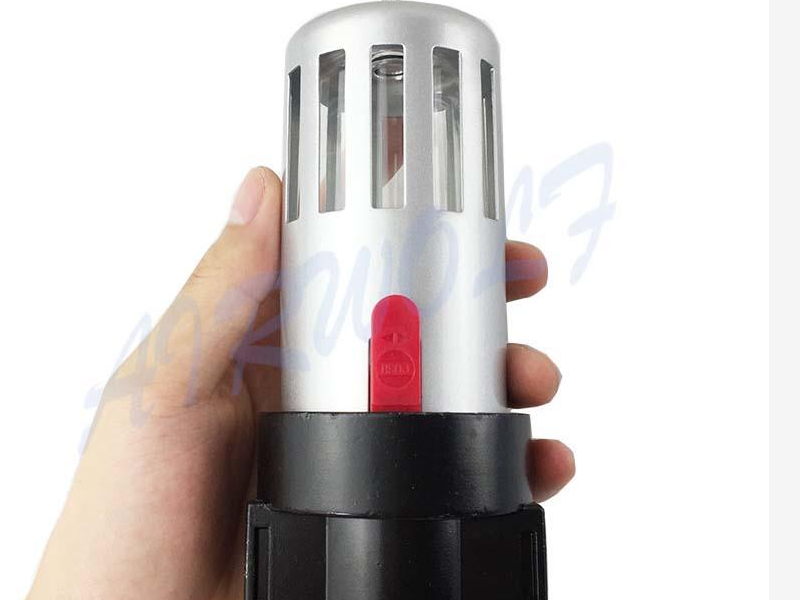
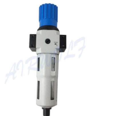
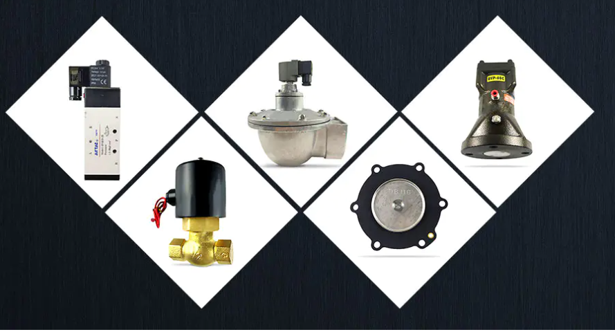
Air zero loss auto drain valve
Auto drain valve
Timer valve
Electronic drain valve
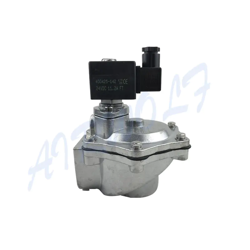
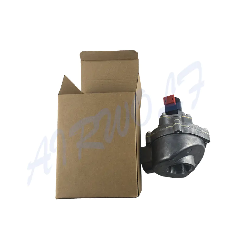
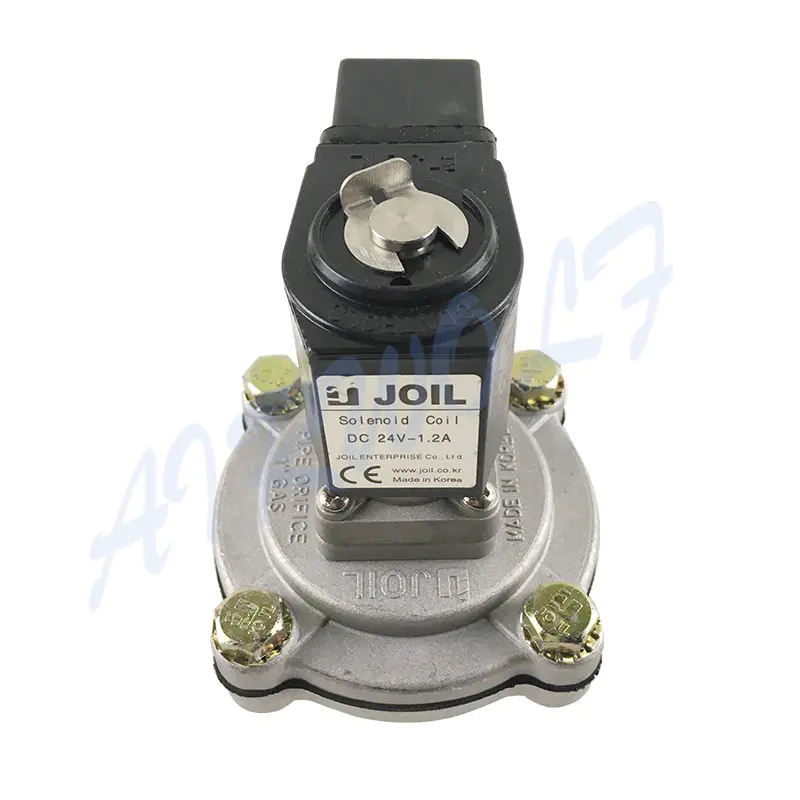
Before each solenoid valve is used, Medium:Must after 40μm filtered air,recommended to add lubricator to prolong the service life.
1.Air compressor
2. Refrigerated dryer
3. Drain valve
4. Air tank
5. Air filter
6. Air regulator
7. Air lubricator
8. Solenoid valve (electromagnetic valve)
9. Pneumatic operated directional valve
10. Air cylinder(pneumatic cylinder)
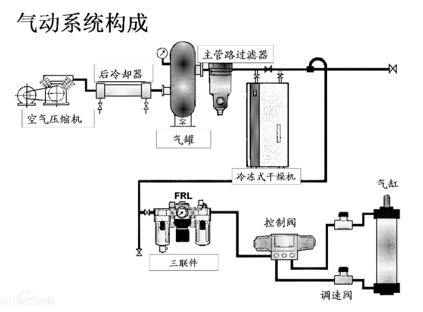
(1)Air source device
The air source device is the energy device for obtaining compressed air, the main part of which is the air compressor, in addition to the air source purification equipment. The air compressor converts the mechanical energy supplied by the prime mover into the pressure energy of the air, while the air source purification equipment is used to reduce the temperature of the compressed air, remove the moisture, oil and pollution impurities in the compressed air. Factories and mines that use more pneumatic equipment often concentrate the air source device in the compressor station (commonly known as the air station), which then uniformly distributes and supplies compressed air to each gas consumption point (branch plant, workshop, gas equipment, etc.).r)
(2)Executive components
The executive component is the energy conversion device which takes the compressed air as the working medium and transforms the pressure of the compressed air into mechanical energy, including the cylinder which does the linear reciprocating motion, the air motor which does the continuous rotary motion,pneumatic actuator and the swing motor which does the discontinuous rotary motion.
(3)Control components
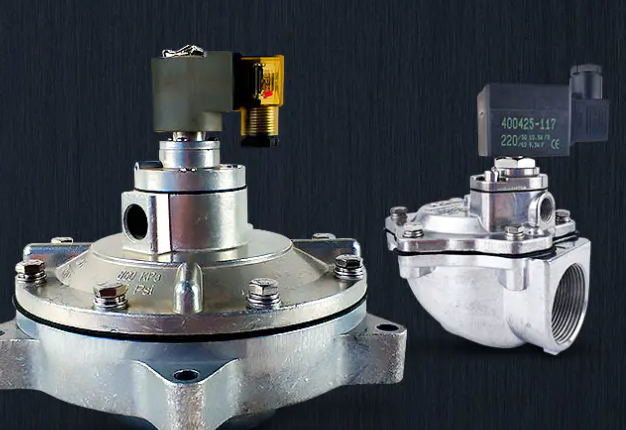
The control component, also known as control, operation and detection component, is used to control the pressure, flow and flow direction of compressed air flow so as to make the actuator complete the predetermined motion law. Including various pressure valves, direction valves, flow valves, logic elements, jet components, stroke valves, converters and sensors.
(4)Auxiliary components
Auxiliary components are the devices needed to purify, lubricate, silence and connect the compressed air. Including water separator, oil mist filter, muffler and various pipeline accessories.
The basic working characteristics of pneumatic transmission: the working pressure of the system depends on the load; the moving speed of the actuator only depends on the input flow, and has nothing to do with the external load.
Pneumatic system features
(1)Advantages
1.The air are available everywhere and inexhaustible, which saves the cost of purchasing, storing and transporting media: the used air is directly discharged into the air, without pollution to the environment; it is convenient to handle, without the need to set a recovery pipeline, so there are no problems such as media deterioration, supplement and replacement.
2.Because the air viscosity is small, the flow resistance in the pipe is small, and the pressure loss is small, which is convenient for centralized air supply and long-distance transportation. Even if there is leakage, it will not pollute the environment like hydraulic oil.
3. Compared with hydraulic drive, pneumatic response is fast, action is fast, maintenance is simple, and pipeline is not easy to be blocked.
4. The structure of pneumatic components is simple and easy to manufacture, which is suitable for standardization, systematization and generalization.
5.The pneumatic system has good adaptability to the working environment, especially in the working environment of inflammable, explosive, dusty, strong magnetic, radiation, vibration, etc., its safety and reliability are better than that of hydraulic, electronic and electrical systems.
6.Air has compressibility, which enables the pneumatic system to realize automatic overload protection, and also facilitates the storage of energy in the air tank for emergency.
7.The temperature of the gas decreases due to expansion during exhaust, so the pneumatic equipment can automatically cool down, and it will not overheat during long-term operation.
(2)Disadvantages
1.The air has compressibility. When the load changes, the action stability of the pneumatic system is poor. But it can be solved by gas-liquid linkage.
2.The working pressure is low (generally 0.4 ~ 0.8MPa), and the output power is small because the structure size should not be too large.
3.The speed of gas signal transmission is slower than that of light and electron, so it is not suitable for the complex circuit requiring high transmission speed. But for general mechanical equipment, the transmission speed of pneumatic signal can meet the requirements.
4.The exhaust noise is large, so the muffler is needed.
Application and development of pneumatic technology
1.2.1
Application scope of pneumatic technology
At present, pneumatic transmission technology is widely used in the following aspects.
①The mechanical manufacturing industry includes the clamping and conveying of the workpiece on the machining production line, the molding and stamping of the casting production line, the combination of boxes, etc., as well as in the automobile manufacturing, the automatic production line, the automatic handling and fixation of the car body parts, the automatic welding, etc.
②Electronic IC and electrical industry, such as handling of silicon wafer, inserting and soldering of components, assembly of household appliances, etc.
③Most of the automation processes of pipeline transportation medium for petroleum and chemical industry use pneumatic transmission, such as oil refining and processing, gas processing, fertilizer production, etc
④The light industrial food packaging industry includes all kinds of semi-automatic or full-automatic packaging production lines, such as wine, oil, gas can and various food packaging, etc
⑤Robots such as assembly robot, painting robot, carrying robot, wall climbing robot, welding robot, etc.
⑥Others such as vehicle brake device, door opening and closing device, particulate matter screening device, torpedo missile automatic control device, etc. The wide use of various pneumatic tools is also an integral part of the application of pneumatic technology.
1.2.2General situation and development trend of pneumatic technology
(1)General situation of development
More than two thousand years ago, people began to use the energy of air to complete all kinds of work. For example, the Greeks used compressed air to increase the range of catapults. But as a dimension of the application of pneumatic technology, John Wilkinson invented the air compressor in about 1776. In the 1920s, pneumatic technology was successfully applied to the opening and closing of automatic doors and the auxiliary actions of various machines, but these are only pneumatic technology as a means of transmission. In the 1960s and 1970s, with the development of industrial mechanization and automation, pneumatic technology has been widely used in various fields of production automation, forming a modern pneumatic technology.
In recent decades, pneumatic technology has not only been used to do work, but also to detect and process data. The development of sensors, process controllers and actuators has led to the generation of pneumatic control systems. In recent years, with the development of electronic technology, computer and communication technology and the further improvement of the performance ratio of various pneumatic components, the advancement and complexity of pneumatic control systems are playing a more and more important role in the field of automatic control.
(2)Developing trend
①combination and intelligence
The most common combination is the cylinder with valve and switch: in the material handling, the combination of cylinder vacuum sucker is also used, and the solenoid valve and program controller are equipped, with compact structure and adjustable space occupation stroke.
②Miniaturization, integration and precision
In addition to miniaturization, non-circular piston cylinder and cylinder with guide rod have been developed at present, which can reduce the swing of piston rod of common cylinder when it works; in order to make the cylinder position accurately, brake cylinder has been developed. In order to make the positioning of the cylinder more accurate, the sensor and proportional valve are used to realize the feedback control. The positioning accuracy is up to 0.01M. In the aspect of precision cylinder, 0.3m/s low speed cylinder and 0.01N small load cylinder have been developed. In the process of gas source treatment, the filter with filter accuracy of 0.01M, filter efficiency of 99.9999% and pressure reducing valve with sensitivity of 0.001wpa have been developed
③High speed
At present, the piston speed range of cylinder is 50 ~ 750mm / s. In order to improve productivity, the pace of automation is accelerating. In the future, the piston speed of the cylinder is required to be increased to 5 ~ 9m / s. Accordingly, the response speed of the valve will also be accelerated, and the requirement will be increased from the current 1 / 90s level to 1 / 900s level.
④Oil free, tasteless and sterile
Due to the increasingly high requirements of human beings for the environment, we do not want the exhaust gas from pneumatic components to pollute the environment with oil mist, so the oil-free pneumatic components will be popularized. Some special industries, such as food, beverage, pharmaceutical, electronic, etc., require more strict air requirements. In addition to oil-free, they also require tasteless, sterile, etc. filters with such special requirements will be continuously developed.
⑤High life, high reliability and intelligent diagnosis function
Pneumatic components are mostly used in automatic production, the failure of components will often affect the operation of the equipment, so that the production line stops working, resulting in serious economic losses, therefore, the engineering reliability of pneumatic components put forward higher requirements.
⑥Energy saving and low power consumption
The low power consumption of pneumatic components can save energy, and can be better combined with microelectronics technology and computer technology. The solenoid valve with power consumption ≤ 0.5W has been developed and commercialized, which can be directly controlled by computer.
⑦Mechanical-electrical integration
In order to accurately achieve the desired control objectives, closed-loop feedback control should be used. In order to realize this control mode, it is necessary to solve the problem of mutual conversion among the digital signal of computer, the analog signal of sensor feedback and the pneumatic control air pressure or air flow.
⑧Application of new technology, process and material
In the manufacturing of pneumatic components, the technologies of profile extrusion, casting infiltration and module assembly have been widely used; new die-casting technologies (hydraulic core pulling, vacuum die-casting, etc.) have been gradually promoted; piezoelectric technology, bus technology, new soft magnetic materials, dialysis membrane, etc. are being applied.
2.1.1Composition of air
Natural air is a mixture of gases. Its main components are nitrogen and oxygen, followed by argon and a small amount of carbon dioxide and other gases. In addition, it also contains a certain amount of water vapor and sand and other fine solids. In cities and factory areas, due to smoke and automobile exhaust, the atmosphere also contains sulfur dioxide, nitrite, hydrocarbons and other substances.
The proportion of nitrogen in the air is the largest. Because the chemical property of nitrogen is not active, stable and will not self ignite, air can be used as a working medium in flammable and explosive places.
2.1.2Humidity of air
(1)Dry and wet air
Air is usually divided into dry air and wet air, with water vapor as the distinguishing mark.
Wet air: air containing water vapor is called wet air. The air in the atmosphere is basically wet air.
Dry air: air without water vapor is called dry air.
The amount of moisture in the air has a direct impact on the stability of the system, so various pneumatic components have clear provisions on the moisture content, and some measures should be taken to prevent the introduction of moisture.
(2)Humidity
The moisture (water vapor) content of wet air is usually expressed in terms of humidity. It can be expressed by absolute humidity, relative humidity and moisture content. .
1.Absolute humidity, the mass of water vapor contained in unit volume of wet air in standard state, is called the absolute humidity of wet air.
2.Saturated absolute humidity refers to the mass of water vapor contained in unit volume of saturated wet air at a certain temperature.
3.Relative humidity refers to the ratio of absolute humidity and saturated absolute humidity under certain temperature and pressure.
4.Moisture content, mass of water vapor contained in unit mass of wet air.
Main performance of air
(1 )Compressibility and expansibility of air
When the pressure of a gas changes, its volume changes accordingly, which is called the compressibility of the gas. The property that the volume of gas changes with the change of temperature is called the expansibility of gas. The compressibility and expansibility of gas are much greater than that of liquid. For example, for the isothermal compression of gas at atmospheric pressure, the pressure increases by 0.1MPa and the volume decreases by half. When the oil pressure is increased by 18 MPa, its volume is only reduced by 1%. When the pressure is constant and the temperature changes 1 ℃, the volume of gas changes about 1 / 273, while the volume of water only changes 1 / 20000, and the capacity of air volume change is 73 times that of water.
The law of gas volume changing with pressure and temperature obeys gas state equation. Gas is easy to compress, which is conducive to gas storage, but the compressibility of gas leads to poor stiffness and positioning accuracy of pneumatic transmission system.
(2)Air viscosity
The viscosity of a fluid means that it has the property of resisting flow. Gas has much less viscosity than liquid, but in fact, gas has viscosity
2.1.5 Air pollution
In order to improve the operation accuracy of the pneumatic system and the service life of the components, the compressed air (working medium) must be well purified to avoid the harm of pollution.
(1)Pollution and harm of compressed air
There are a certain amount of water, oil and dust impurities in the air. If the purification treatment is improper, these pollutants will cause many adverse effects on the system once they enter the pneumatic system. Therefore, the compressed air used in the pneumatic transmission system can only be used after being dried and purified. The pollution impurities of compressed air mainly come from the following aspects:
①When the filter device at the suction port of the air compressor in the external suction system is not used properly, the suction force of the air compressor will suck in the dust, other mixtures and other impurities in the air. If the subsequent purification is not complete, some impurities will be mixed into the system, which will damage the operation accuracy of the system and cause wear of the moving elements, thus reducing the service life. In addition, even when the system is shut down, external impurities will enter the system from the exhaust port of the valve, causing pollution damage.
②Impurities generated in the system during operation the lubricating oil on the relative moving surface inside the air compressor will deteriorate and generate oil sludge under high temperature. The rust generated by the corrosion of components or pipes due to cavitation, as well as the residual sand and welding slag during component casting and welding, etc. these pollutants will block the orifice and valve core and cause wear of moving components.
③Improper protection or incomplete cleaning of pollutants left during system installation and maintenance will leave some pollutants in the system and cause pollution during operation.
(2)Air quality level
The quality of compressed air mainly refers to the degree of pollution. For different pneumatic systems, there should be different requirements. Therefore, it is necessary to reasonably control the pollution indexes such as solid dust particles, water content and oil content contained in the compressed air according to the specific conditions of the system.
(1) Pollution and hazards of compressed air:
The air contains a certain amount of moisture, oil and dust impurities. If the purification is not properly treated,
once these pollutants enter the pneumatic system, it will cause many adverse effects to the system. Therefore,
the compressed air used in the pneumatic transmission system must be dried and purified before it can be used.
The pollution impurities of compressed air mainly come from the following aspects.
① The external filter is sucked into the system, and the filter device of the air compressor suction port is not used properly. The suction of the
air compressor will inhale impurities such as dust and other mixture in the air. If the subsequent purification is not complete, some impurities
will be caused. Mixing into the system, destroying the operating accuracy of the system and causing wear and tear on the moving parts to
reduce the service life. In addition, even if the system is shut down, foreign impurities will enter the system from the wide exhaust port,
causing pollution damage.
②The impurities generated inside the system during operation, the lubricating oil on the opposite moving surface of the air compressor will
deteriorate under high temperature to form sludge, the rust generated by corrosion of components or pipelines due to cavitation, and the
sand remaining during casting and welding of components. Such as welding slag, these contaminants will block the orifice, the spool, and
cause the moving parts to wear.
③Contaminants left over from system installation and maintenance. Improper protection, or incomplete cleaning, will leave some pollutants inside the system and cause pollution during operation.
The natural air contains some solid particles, dust and moisture. When compressed, some of the lubricating oil in the compressor will be mixed into the compressed air. Therefore, the compressed
air generated by the compressor is actually a compressed air containing various impurities such as solid dust, carbon powder, water, and oil. In a pneumatic system, the direct use of such unpurified gas can reduce or damage the life of the pneumatic component, causing malfunction of the pneumatic system, resulting in reduced production efficiency and increased maintenance costs.
Therefore, compressed air purification treatment is an indispensable part of the pneumatic system. Purification of the compressed air is to remove the moisture, oil, solid dust and carbides in the air that affect the normal operation of the pneumatic system to meet the normal working needs of the system.
The equipments used to produce, process, and store compressed air is referred to as air source units.
The function of the air supply unit is to provide clean, dry compressed air with a certain quality requirement for the pneumatic system.
The compressed air discharged by the air compressor, although capable of meeting certain pressure and flow requirements, cannot be used by pneumatic devices.
Because the air compressors used in general pneumatic equipment are low-pressure (less than 1 MPa), oil-lubricated piston air compressors, which draw air from the atmosphere containing moisture and dust, after compression, air temperature Will increase to 140 - 180 ° C, when the oil in the air compressor cylinder is also partially gaseous. In this way, the oil, moisture and dust form a mixed colloidal dust and the impurities are mixed together in the compressed air.
If you convert this compressed air directly used for pneumatic devices, will affect the normal operation of the pneumatic system.
Source of impurities in compressed air:
1. Moisture and dust entering from the suction port of the compressor.
2. Condensed water produced by cooling after the atmosphere is compressed.
3. During the compression process, the lubricant deteriorates and becomes a sludge.
4. Metal powder produced by rust and moving friction parts of pipes and pneumatic components.
The necessity of air purification treatment:
1. The oil vapor mixed in the compressed air may accumulate in the container of the gas storage tank, the pipeline and the pneumatic system to form a flammable substance, which may cause the explosion; on the other hand, after the lubricating oil is vaporized, an organic acid is formed, Metal equipment and pneumatic devices have corrosive effects that affect the life of the equipment.
2. Impurities mixed in the compressed air are deposited in the channels of the pipe and pneumatic components, reducing the passage area and increasing the pipe resistance. In particular, some pneumatic components with an inner diameter of only 0.2 - 0. 5mm will cause blockage, so that the pressure signal will not be transmitted correctly, and the entire pneumatic system will not work stably or even fail.
3.The saturated water contained in the compressed air will condense into water under certain conditions and accumulate in individual pipes.
In the cold winter, the condensed water will cause damage to the pipes and accessories, which will affect the normal operation of the pneumatic device.
4.Impurities such as dust in the compressed air will cause grinding action on the moving parts of the pneumatic components (such as cylinders, air motors, pneumatic reversing valves, etc.) that reciprocate or rotate in the pneumatic system, so that these components are reduced due to air leakage. Efficiency affects its service life? Therefore, the air source device must be equipped with some air source purification treatment auxiliary equipment for removing oil,removing water and dust, and drying the compressed air to improve the quality of the compressed air.
The cylinder is a component used to realize linear motion and perform external work. Its structure and shape have various forms, and there are many classification methods.
Commonly used are the following:
1. According to the driving method: single-acting cylinder, double-acting cylinder.
2. According to the structural characteristics: piston cylinder, vane cylinder, membrane cylinder, Air-liquid damping cylinder.
3. According to the installation method: ear seat type cylinder, flange type cylinder, shaft pin type cylinder, flange type cylinder.
4. According to size specifications: micro, small, medium, large.
5. According to the cylinder function points: ordinary cylinders and special cylinders.
Ordinary cylinders mainly refer to piston single-acting cylinders and double-acting cylinders; special cylinders include gas-liquid damping cylinders, membrane type
Cylinders, impact cylinders, booster cylinders, stepping cylinders, rotary cylinders, etc.
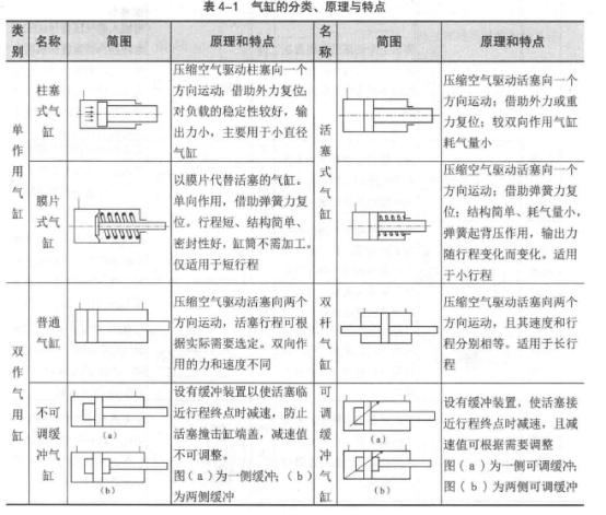
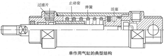
Single-acting cylinder means that compressed air only inhales at one end of the cylinder and pushes the piston to move, while the return of the piston is a cylinder that works by means of other external forces such as gravity, spring force, and the like. The typical structure of a single-acting cylinder is shown in the figure.
Single-acting cylinders have the following features:
①1. Due to the single-side air intake, the structure is simple and the air consumption is small.
②Due to the spring return, the energy of the compressed air is partially used to overcome the reaction force of the spring, thereby reducing the output thrust of the piston rod.
③The space inside the cylinder is reduced by the installation of the spring, which shortens the effective stroke of the piston.
④The spring force of the cylinder return spring varies with the magnitude of its deformation, so the thrust and speed of the piston rod vary during the stroke. Single-acting piston cylinders are often used for short strokes and where the thrust and speed of the piston rod are not critical, such as positioning and clamping devices.
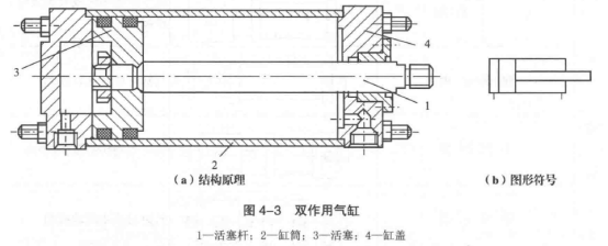
The figure below shows the typical structure of a double-acting single rod cylinder. Double acting means that the reciprocating motion of the piston is driven by compressed air. In the cylinder of a single piston rod, because the area on the left side of the piston is relatively large, when the air pressure acts on the left side, a slow and powerful working stroke is provided; when the stroke is returned, since the area on the right side of the piston is small, the speed is relatively high. Fast and the force is getting smaller. The figure shows the graphical symbols of the double-acting single-rod cylinder, which is also commonly used as a general graphical symbol for cylinders.
Double-acting cylinders are the most widely used and are generally used in packaging machinery, food machinery, processing machinery and other equipment.
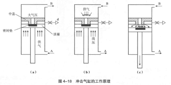
1. Buffer cylinder:
The cylinder with a cushioning device on the cylinder head is called a buffer cylinder. Commonly used cushioning devices are air cushion cushioning devices, rubber cushions and hydraulic shock absorbers.
Air cushion cushioning is achieved by compressing a fixed volume of air at the end of the cylinder stroke. The structural principle is as shown in the figure. Before the piston enters the buffer stroke, the air is discharged from the normal exhaust port. After entering the buffer stroke, the remaining accumulation accumulates in the compression chamber. The air inside can only be slowly discharged through the adjustable flow valve to achieve the purpose of decelerating the piston, which is buffered at the end of the stroke. Commonly used buffer devices consist of a throttle valve, a buffer plunger, a check valve, and a buffer seal.
In the case where it is not necessary to use the cushion cushioning method, the rubber cushion is used as the cushioning member to fully meet the requirements for use. The elastic rubber gasket is installed at both ends of the piston. When the piston runs to the end, the rubber gasket contacts the cylinder head to cushion.
2. Hydraulic buffer:
In the case where the cylinder piston has a relatively high moving speed and a relatively large drag load, it is likely to cause a large impact. In this case, a hydraulic shock absorber can be installed on the end plate to absorb relatively large kinetic energy and serve as a buffer.
When kinetic energy is transmitted to the head of the damper piston, the damper establishes oil pressure at the bottom of the piston, as shown in Figure b. The pressure of this oil pressure can be gradually released through the release orifice in the inner tube of the buffer to absorb the kinetic energy and buffer the inertial impact.
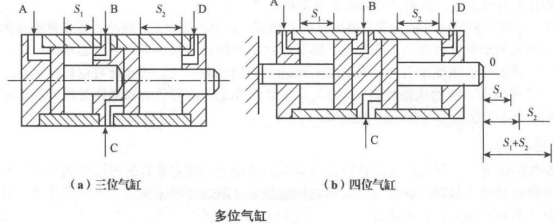
(2) Multiple cylinders:
The plurality of cylinders are connected in series, and a plurality of cylinders are called by setting the strokes of the respective cylinders to obtain a plurality of cylinders at the stop positions. Its structural principle is shown in the figure. Figure a shows a three-position cylinder, which is a two-piston cylinder formed by two ordinary double-acting cylinders connected in series. The strokes of the two pistons are S1, S2, respectively, and S1 < S2. When the air pressure is not input to the four ports, the cylinder is at the 0 position, the cylinder piston rod is extended to the position 0; when the A port is input with the air pressure, and the B port is exhausted, the cylinder piston rod is
The extended position is S1; when the C port inputs the air pressure, and the D port is exhausted, the cylinder piston rod extends out to the position S2; after the D port inputs the air pressure, the C port is exhausted and the cylinder is reset. That is, the cylinder piston rod has three extended stop positions, namely 0, S1 and S2.
Figure b shows a four-position cylinder, which is a two-piston cylinder that is connected by two ordinary double-acting cylinders of the same cylinder diameter. The two piston strokes S1, S2 may be the same or different, and the pistons move in opposite directions. When one end of the piston rod is fixed, the piston rod at the other end of the cylinder has four stop positions, namely 0, S1, S2, and S1+S2.
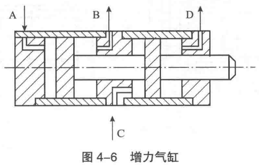
3. Booster cylinder
As shown in the figure, the two double-acting cylinders with the same cylinder bore are connected in series to form a booster cylinder. Since the two pistons are connected in series on one piston rod, the output force is increased by one-fold compared to the cylinder of one piston. Such cylinders are often used in applications where it is desirable to increase the cylinder output force without increasing the cylinder diameter, but allowing the cylinder to be enlarged.
(4) Slide cylinder
The figure below shows the slide cylinder. It consists of two double-piston double-acting cylinders connected in parallel, and the principle of operation is the same as that of ordinary cylinders. The two cylinder chambers communicate with each other through the air guiding holes on the middle cylinder wall to ensure that the two cylinders operate simultaneously. It is characterized by double the output of the cylinder and light weight, saving installation space. There are two types of installation methods: slide type and side seat. Suitable for applications such as pneumatic manipulators.
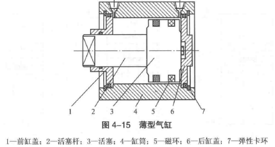
(1) Ordinary rodless cylinder: The rodless cylinder does not have a rigid piston rod of a common cylinder, and it uses the piston to reciprocate directly or indirectly. The biggest advantage of this type of cylinder is that it saves installation space, especially for small bore and long stroke. The pistonless cylinders mainly include mechanical contact cylinders, magnetic coupling cylinders, steel cable cylinders and steel cylinders. The first two rodless cylinders have gained a large number of applications in pneumatic automation systems and pneumatic robots. A mechanically coupled rodless cylinder is generally referred to as a rodless cylinder, and a magnetically coupled cylinder is referred to as a magnetic cylinder. This will not be confused, and the title is convenient.
(2)The magnetic rodless cylinder has a piston that synchronously moves the moving body outside the cylinder by magnetic force, and the structure is as shown in the following figure. Its working principle and characteristics are to install a set of high-strength magnetic permanent magnet rings on the piston. The magnetic lines of force pass through the thin-walled cylinder tube and another set of magnetic rings that are placed outside. Since the two sets of magnetic rings have opposite magnetic properties, they have strong suction. When the piston is pushed by the air pressure in the cylinder, the magnetic ring sleeve outside the cylinder is moved together under the action of the magnetic force. The thrust of the cylinder piston must be adapted to the suction of the magnetic ring.
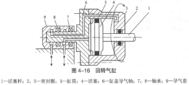
Rotary cylinder
The figure shows a rotary cylinder. The cylinder cylinder is connected to the rear end of the machine tool spindle by a transition flange, and rotates with the main shaft, and the air guide sleeve does not move, and the air guide shaft of the cylinder body can rotate relative to each other in the air guide sleeve. While the cylinder random bed main shaft rotates together, the piston reciprocates. The radial hole end of the air inlet and exhaust holes of the air guiding sleeve communicates with the inlet and exhaust grooves of the air guiding shaft.
The air guiding sleeve and the air guiding shaft are required to rotate relative to each other, and are equipped with a rolling bearing and sealed with a grinding gap.
Rotary cylinders are generally used in conjunction with pneumatic chucks to control the loosening and clamping of the workpiece by the advancement and retreat of the cylinder pistons, which are used for automatic clamping of machine tools.

Guide cylinder:
As shown in the figure, The cylinder for preventing the piston rod revolving device is provided, which is called the Guide cylinder. Various types of cylinders can be provided with different guiding devices as needed.
1.1. Selection principle of cylinder:
(1) Select the structure and installation method of the cylinder according to the requirements of the work movement.
(2) Determine the thrust and tension of the piston rod according to the force required by the working mechanism.
(3) The output force of the cylinder is determined according to the magnitude of the cylinder load force, thereby calculating the cylinder bore of the cylinder.
(4) Determine the itinerary according to the requirements of the work organization's tasks. Generally, full strokes are not used.
(5) Determine whether a buffer device should be used depending on the speed of the piston.
(6) The recommended cylinder working speed is about 0.5~1m/s, and the pipeline and control components are selected according to this principle. For high-speed moving cylinders, the intake pipe with a large inner diameter should be selected. For the case where the load changes, a speed control valve or a gas-liquid damping cylinder can be selected to achieve slow and stable speed control.
(7) If the cylinder is working in a harsh environment such as dust, install a dust cover on the protruding end of the piston rod. No oil or oil-free cylinders are required when no pollution is required.
2. Precautions for cylinder installation and use:
(1) Before using the cylinder, check whether the installation connection points are loose or not: safety interlock should be considered in operation; when performing sequential control, check the working position of the cylinder; when the fault occurs, there should be emergency stop device; After that, the compressed air inside the cylinder should be discharged.
(2) When the cylinder is used in a dusty environment, a dust cover should be placed on the piston rod. The filter hole of the single-acting cylinder should be fitted with a filter to prevent dust from being sucked from the breathing hole.
(3) For cylinders that need to be lubricated with oil mister, the lubricant should be selected so that the seal does not expand and contract, and it does not emulsifie with the moisture in the air.
(4) Before the cylinder is connected to the pipeline, the dirt inside the pipeline must be removed to prevent debris from entering the cylinder.
(5) The cylinder piston rod is subjected to the axial force. During installation, it is necessary to prevent the lateral load from being applied during the cylinder operation. The lateral load allowed to bear is only 1 / 20 of the maximum thrust of the cylinder. When adopting flange type and foot seat type installation, the installation bolt itself should be prevented from being directly subjected to thrust or tensile load; when the tail suspension is used for intermediate swing installation, the position of the connecting pin at the top of the piston rod is in the same direction as the position of the mounting shaft; When swinging the intermediate shaft pin, pay attention to the position of the connecting rod of the top end of the piston rod, and pay attention to the verticality of the cylinder axis and the shaft bracket. At the same time, the pendulum frame is placed as close as possible to the root of the pendulum shaft within the range where no jam occurs.
(6) After the cylinder is installed, it should be reciprocated several times with no load to check whether the movement of the cylinder is normal. Then connect the load and adjust the speed. First, the speed control valve is opened in the middle position, and then the output pressure of the pressure reducing valve is adjusted. When the cylinder approaches the specified speed, the set pressure can be determined. Then fine-tune with the speed control valve. Before starting the buffer cylinder, the buffer throttle valve is rotated at a position where the throttle amount is small, and then gradually opened until a satisfactory buffering effect is achieved.
(7) The ideal working temperature of the cylinder is 5~60°C. When the temperature is too high or too low, corresponding measures should be taken. The cylinder should be used below 5 °C. To prevent condensation of water vapor in the compressed air, consider the type of seal and the type of lubricant used at low temperatures. In addition, the air in the low temperature environment will condense on the piston rod. For this reason, it is better to use infrared heating to prevent freezing on the piston rod. When the cylinder frequency is low, the piston rod can be greased so that the piston rod does not freeze. When using at high temperatures, consider the heat resistance of the cylinder material. Use a heat-resistant cylinder and pay attention to the effect of high-temperature air on the reversing valve.
Pneumatic finger cylinders are also called air fingers or air grippers. Its function is to achieve a variety of grabbing functions, is a key component of modern pneumatic manipulators. According to the number of gas fingers, it can be divided into two-finger cylinder, three-finger cylinder and four-finger cylinder. According to the different forms of movement of the finger, it can be divided into parallel moving fingers and swinging fingers
1. Parallel finger cylinder:
The fingers of the parallel finger cylinder shown in the figure are actuated by two pistons. Each piston is connected to a pneumatic finger by a roller and a double crank to form a special drive unit. Thus, the pneumatic finger always moves axially toward the heart, and each finger cannot move alone. If the finger moves in the opposite direction, the previously pressurized piston is in the exhaust state while the other piston is in the pressurized state.
2. Three-point finger cylinder
As shown, the three-point finger cylinder has an annular groove on the piston. Each crank is connected to a pneumatic finger. The piston movement can drive three crank movements, thus controlling three fingers to open and close at the same time.
3. Swing finger cylinder
The piston rod of the oscillating finger cylinder shown in the figure has an annular groove. Since the finger trunnion is connected to the annular groove, the fingers can be simultaneously moved and automatically centered, and the grasping torque is always constant.
(4) Rotating finger cylinder
The action of rotating the finger cylinder shown in the figure is based on the meshing principle of the rack and pinion. The piston is fixed with the shaft that can be moved up and down. The end of the shaft has three annular grooves that engage the teeth of the two drive wheels. Thus, the pneumatic finger can be moved and automatically centered at the same time, and the gripping torque is always constant.
The function and type of pneumatic control valve:
The pneumatic control component is also a pneumatic control valve. Its function is to control and adjust the pressure, flow, flow direction and transmission signal of the compressed air. They can be used to form various pneumatic control loops, so that the pneumatic actuator can work normally according to the designed procedure. .
Pneumatic control components can be divided into three categories: directional control valve, pressure control valve and flow control valve according to function and use. In addition, there are pneumatic logic components and fluidic components that achieve various logic functions by changing the direction of the airflow and switching. In recent years, with the miniaturization of pneumatic components and the large number of applications of PLC control in pneumatic systems, the application range of pneumatic logic components is gradually decreasing.
From the control method, the pneumatic control can be divided into two types: intermittent control and continuous control. In the intermittent control system, the pressure control valve, the flow control valve and the directional control valve are usually used to realize the program action; in the continuous control system, in addition to the pressure control valve and the flow control valve, the servo control valve is also used. Proportional control valves, etc., for continuous control of the system. The classification of pneumatic control valves is shown
2. Features of pneumatic control valve:
Pneumatic control valves have the following characteristics compared with hydraulic valves:
(1) Different energy sources used:
Pneumatic components and devices can be operated by air compressors in a centralized manner, and the working pressure of the respective pressure reducing valves can be adjusted according to the requirements of use and control points. The hydraulic valves are equipped with a return line for the tank to collect used hydraulic oil. The pneumatic control valve directly discharges compressed air to the atmosphere through the exhaust port.
(2) Different requirements for leakage:
The hydraulic valve requires strict leakage to the outside, while a small amount of leakage inside the component is allowed. For pneumatic control valves, internal leakage is not permitted in principle except for gap-sealed valves. Internal leakage of pneumatic control valves poses a risk of accidents. For pneumatic piping, a small amount of leakage is allowed; and leakage of hydraulic piping will cause system pressure drop and environmental pollution.
.
(3) Different requirements for lubrication
The working medium of the hydraulic system is hydraulic oil. The hydraulic valve does not have the requirement of lubrication. The working medium of the pneumatic system is air, and the air is non-lubricating. Therefore, many pneumatic valves require oil mist lubrication. Valve parts should be selected from materials that are not susceptible to water corrosion, or take necessary rust prevention measures.
(4) different pressure ranges
Pneumatic control valves have a lower operating pressure range than hydraulic valves. The working pressure of the pneumatic control valve is usually within 1 MPa, and a few can reach within 4 MPa. However, hydraulic valves have a high working pressure (usually within 50 MPa). If the pneumatic control valve is used above the maximum allowable pressure, serious accidents will often occur.
(5) Different use characteristics
The general pneumatic control valve is compact and lighter than the hydraulic valve, and is easy to integrate and install. The valve has a high operating frequency and a long service life. The low-power solenoid valve with a power of only 0. 5W has been developed in the direction of low power and miniaturization. It can be directly connected to the microcomputer and the programmable controller, or it can be installed on the printed circuit board together with the electronic device, and the air circuit is connected through the standard board, which saves a lot of wiring, and is suitable for pneumatic industrial manipulators and complicated production. Manufacturing assembly lines andd other occasions.
Directional control valve:
The pneumatic directional control valve is a pneumatic component in the pneumatic transmission system that controls the starting, stopping and moving direction of the actuator by changing the flow direction of the compressed air and the on and off of the air flow.
The directional control valves can be divided into different types according to the function of the directional control valve, the control mode, the structural form, the direction of the airflow in the valve, and the sealing form.
Classification of directional control valves
Classification, form
According to the flow direction of the gas in the valve: check valve, reversing valve
According to the structure of the spool: shut-off valve, spool valve
Sealed by valve: hard seal, soft seal
Number of working digits and number of channels by valve: 3/2way, 5/2way, 5/3way, etc.
Control operation mode according to valve: air pressure control, electromagnetic control, mechanical control, manual control
2.1 check valve:
The check valve only allows gas to flow in one direction. Commonly used check valves include ordinary check valves, pneumatic check valves, shuttle valves, dual pressure valves, and quick exhaust valves.
(1) Ordinary check valve:
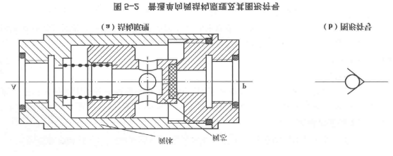
Ordinary check valves only allow airflow to pass in one direction and completely close in the opposite direction, as shown in Figure 5-2 (a), where the spool is closed by spring force. After the air pressure is added to the P port, the air pressure acting on the valve core opens the valve core against the spring force and the friction force, and the P port and the A port are connected. The flow of air from the P port to the A port is called forward flow. In order to ensure a steady flow of air from the P port to the A port, a certain pressure difference should be maintained between the P port and the A port to keep the valve in the open position. If air pressure is added to port A, port A and port P will not pass, that is, the airflow cannot flow in the opposite direction. The role of the spring is to increase the seal and prevent low pressure leakage. In addition, the valve is quickly closed during reverse flow. Figure 5-2 (b) is its graphical symbol.
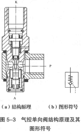
(2) Air control check valve
The air control check valve has a control port K port (Fig. 5-3) than the ordinary check valve. When the K port does not pass the control gas, the air control check valve has the same function as the ordinary check valve, that is, the air flow from the P. The mouth flows to the A port, but cannot flow from the A port to the P port. If the K port is connected to the control gas, under the action of the control gas, the valve core is opened, and the gas can flow backward through the A port to the P port.
(3) Shuttle valve:
Figure 5-4 shows the OR gate shuttle valve. The working characteristic is that no matter which channel of the P1 port and the P2 port is separately ventilated, the path between the port and the port A can be turned on; when the P1 port and the P2 port are simultaneously ventilated, which end is high in pressure, and the end of the port A is connected. The other end is closed and its logical relationship is "or".
OR gate shuttle valves are widely used in logic loops and program control loops. Figure 5-5 shows a common or gate shuttle valve for manual-automatic loop transitions.
(4) Double pressure valve
The function of the dual pressure valve is equivalent to the AND logic function. Figure 5-6 shows a dual pressure valve with two input ports P1 and P2 and one output port A. Only when the P1 port and the P2 port have input at the same time, the A port has an output.
The circuit shown in Figure 5-7 is an application example of the double pressure valve in the hydraulic system of the machine tool. The circuit can reliably ensure the positioning and clamping before drilling.
(5) Quick exhaust valve
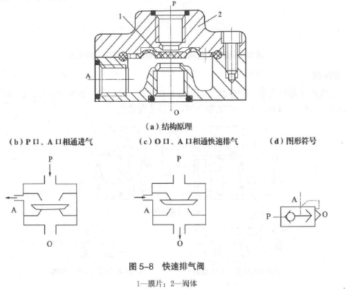
The quick exhaust valve is a special valve set to quickly exhaust the cylinder and speed up the movement of the cylinder, and is installed between the reversing valve and the cylinder. Figure 5-8 (a) shows the structural principle of the quick exhaust valve. When the P port is inflated, push the diaphragm to deform downward, open the passage of the P port and the A port, close the 0 port, as shown in Figure 5-8 (b); when the P port has no intake air, the gas at the A port Push the diaphragm to reset, close the P port, and the A port gas is quickly discharged through the 0 port, as shown in Figure 5-8 (c). Fast exhaust valve graphic
The symbol is shown in Figure 5-8 (d).
Figure 5-9 shows the application circuit for a quick exhaust valve that allows the rodless chamber of the cylinder to be vented without a reversing valve.
2.2 Reversing valve:
The reversing valve is a control valve that can change the flow direction of the airflow. It changes the direction of the air flow by changing the airflow passage, thereby changing the direction of movement of the pneumatic actuator.There are many classification methods for the reversing valve: according to the valve core structure, it can be divided into the cut-off type and the slide valve type; according to the control mode, it can be divided into air pressure control, electromagnetic control, manual control and mechanical control; according to the working principle, it can be divided into direct-acting type; pilot type; by number of digits, the number of ports can be divided into two, three, two, three, four, five and so on.
(1) Basic structure and working principle of the reversing valve
1 Cut-off reversing valve Figure 5-10 shows the structural principle and graphical symbol of the two-position three-way single air-controlled cut-off type reversing valve. The figure shows the state when the K port has no control signal, and the spool 3 is in the spring 2 Move to the right under the pressure of the P cavity, so that the P port is disconnected from the A port, and the A port is connected to the T port; when the K port has a control signal, the piston 5 is pushed through the spool compression spring to open the channel of the P port and the A port. , the passage of the A and T ports is closed. Figure 5-10 shows the normally-off type valve. If the P port and the T port are connected, it will become a normally open type. Here, the reversing spool is indexed by a pressurized method.
2. Slide-type reversing valve: The cylindrical valve core is moved axially in the cylindrical valve sleeve to switch the gas path. Figure 5-11 shows the structural principle of the spool type directional control valve. Figure 5-11 (a) shows the initial state of the valve, the spool is moved to the right by the spring force. At this time, the compressed air flows from the input port P to the output port A, the port A has a gas pressure output, and the port B has no air pressure output. Figure 5-11 (b) shows the working state of the valve. The sliding column is moved to the left under the force of the operating force against the spring force. The passage of the P port and the A port is closed, and the P port and the B port are connected. Therefore, the B port has an output, and the A port has no output.
The sliding column type reversing valve can realize the functions of the two-position three-way valve and the two-position five-way valve by slightly changing the size and shape of the valve sleeve or the sliding column.

(2) Number of ports and number of ports of the reversing valve:
1. Number of ports: The basic function of the reversing valve is to create a switching effect on the flow of gas. A reversing valve can open and close several circuits at the same time, so that one of the circuits is in the on state and the other circuit is in the off state, or several circuits are simultaneously cut off. In order to express such switching performance, the number of passages (number of ports) of the reversing valve can be expressed.
The two-way valve has two ports, the input port (indicated by P) and the output port (indicated by A), which can only control the opening and closing of the flow channel. According to the state of the static position of the P→A path, it is further divided into a normally open two-way valve and a normally closed two-way valve. The three-way valve has three ports, in addition to P and A, there is also an exhaust port (indicated by 0). According to the state of the P→A, A→0 path rest position, it is also divided into two types of three-way valves: normal and normally closed.
2. Number of Positions: Refers to the number of switching states of the reversing valve. The valve with two switching states is called a two-position valve, and the valve with three switching states is called a three-position valve. The valve with more than three switching states is called the multi-position valve.
The two-position valve usually has two two-way, two-position three-way, two-position four-way, two-position five-way and the like. The two-position valve has two kinds of reset modes; one is the automatic reset type which can be restored to the original state after canceling the operating force; the other is the valve which cannot be automatically reset (unless the reverse operating force is added), the valve Called memory type.
The three-position valve usually has three position three-way, three-position four-way, three-position five-way and the like. Among the three-position valves, the intermediate position state has three states: medium pressure, medium unloading, and medium pressure.Table 5-2 shows the number of passages and the number of switching positions of the pneumatic directional control valve.
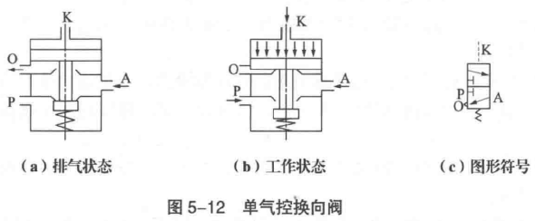

b. Pressure relief control: refers to the control method that the pressure value of the control signal applied to the valve core is gradually decreased. When the air pressure drops to a certain value, the valve is switched. The switching performance of the pressure relief control valve is not as good as the pressure control valve.
c. Differential pressure control: It is a control method that uses the effective area of the air pressure at both ends of the valve core to change the pressure of the valve core to make the spool operate and change direction.
Figure 5-14 shows the graphical symbol of the two-position five-way differential pressure control reversing valve. When the K port has no control signal, the P port communicates with the A port, and the B port communicates with the 02 port. When the K port has a control signal. The P port is connected to the B port, and the A port is connected to the O1 port. The differential pressure controlled spool is reset by air pressure and does not require a return spring.
d. Delay control: The working principle is to use the airflow to be throttled through small holes or gaps, and then inflate into the air chamber. After a certain period of time, when the pressure in the air chamber rises to a certain value, the spool is pushed and the direction is reversed. To achieve the purpose of signal delay.
Figure 5-15 shows the 2/2-way delay control reversing valve, which consists of two parts: delay and commutation. The working principle is that when the K port has no control signal, the P port is disconnected from the A port, the A port is connected to the O port, and the A cavity is exhausted; when the K port has a control signal, the control air flow is first passed through the adjustable flow valve. Then to the temperament. Since the flow rate after the throttling is small, the gas pressure in the gas volume increases slowly. After a certain period of time, when the gas pressure in the gas volume rises to a certain value, the valve core is displaced, so that the P port commun.

2. Electromagnetically controlled reversing valve is a valve that generates electric force on the armature by energizing the electromagnet, and uses this electromagnetic force to realize switching of the valve to change the direction of the airflow. Because this valve is easy to realize combined control of electricity and gas, it can realize long-distance operation, so it has been widely used.The type of electromagnetic control reversing valve is divided into direct-acting and pilot-operated according to the principle; it is divided into single electric-controlled reversing valve and double electric-controlled reversing valve according to the number of control electromagnets.a. Direct-acting electromagnetic reversing valve: A valve that is driven by the armature of an electromagnet to push the reversing valve spool is called a single electrically controlled reversing valve. The single electronically controlled reversing valve has two types: a single electronically controlled direct acting reversing valve and a single electrically controlled pilot operated reversing valve.Figure 5-16 shows a single electronically controlled direct-acting electromagnetic reversing valve that relies on the interaction of an electromagnet and a spring to shift the spool to achieve reversing. Figure 5-16 (a) shows that when the solenoid is not energized, the P and A ports are open and the valve is not output. Figure 5-16 (b) shows that when the solenoid is energized, the electromagnet pushes the spool down, so that the P port and the A port are connected, and the valve has an output. Figure 5-16 (c) shows the graphical symbols.

Copyright © 2025 LV-pneumatic. | All Rights Reserved